Additive‑manufacturing engineers now have a menu of carbon‑fibre‑filled filaments, but the performance gap between chopped and milled fibres often gets blurred. By pulling together three recent sources—the García et al. review (2022) [1], the Wevolver article on reinforcement geometry [2], and the overview of carbon‑fiber 3‑D printing [3], we can clarify how fibre geometry, length, and grade translate into stiffness, dimensional accuracy, and even electrical behaviour.
DEBUNKING - Carbon Fibre Filament Stronger?
Carbon Fiber does not make parts inherently stronger, in most case its can reduce layer adhesion strength (Z) compare to the baseline materials [3] [4].
There's a conversation out there, assessing that Carbon Fiber infused polymers are just for looks, they add no strength, and while they might add to stiffness, they effectively weaken parts, it also can help with printability of some engineering materials reducing the barrier of entry to some materials. [3]
There are three main reasons not related to cosmetic/looks to add Carbon Fiber to your polymer, specifically your 3D Printed part:
- Improving Stiffness in XY, Strength-to-Weight ratio
- Improve Dimensional Accuracy (less warping, shrinkage)
- Improved Electrical Resistivity
Geometry, Length, and Grade
| Feature | Chopped Fibres | Milled Fibres |
|---|---|---|
| Typical length | 200 µm – 5 mm (derived from 6 mm strands, reduced to ~200‑300 µm during extrusion) | ~100 µm (powder‑like) |
| Aspect ratio | High (cylindrical) * can vary between manufacturers | Low (irregular particles) |
| Typical grades | Industrial‑grade (e.g., Nylon) or aerospace‑grade (e.g., PEEK, PET, PPS, PPA) strands | Generic milled carbon, lower cost |
| Alignment during extrusion | Fibres tend to align with flow, creating anisotropic stiffness | Particles stay isotropic |
The aspect ratio is the primary driver of mechanical reinforcement. High‑aspect‑ratio chopped strands act like tiny load‑bearing bridges, while milled particles behave more like a stiff filler [1] [2].
Comparison Table
Below is a detailed comparison of their key properties to help engineers evaluate which reinforcement type suits their project needs.
|
Property |
Chopped Carbon Fibre |
Milled Carbon Fibre |
|
Tensile Strength |
High |
Moderate |
|
Dimensional Accuracy |
Moderate |
High |
|
Flexural Strength |
High |
Moderate |
|
Surface Finish |
Rougher |
Smooth |
|
Aspect ratio |
High |
Low |
|
Printability |
Moderate |
Excellent |
|
Shape |
Chopped Long Strands |
Fine powder |
|
Thermal Conductivity |
High |
Moderate |
|
Moisture Absorption |
Low |
Very Low |
Table Source: https://www.wevolver.com/article/the-role-of-reinforcement-geometry-in-boosting-3d-printed-part-performance [2]
Mechanical Impact – Stiffness & Strength‑to‑Weight
| Metric | 0 % carbon (baseline) | 20 % milled carbon | 10 % chopped carbon |
|---|---|---|---|
| Tensile modulus (approx.) | 1.95 GPa | 6.0 GPa | 8.5 GPa |
| Strength‑to‑weight gain | – | +≈200 % | +≈340 % |
Numbers from VisionMiner illustrate the jump in stiffness when moving from milled to chopped reinforcement [3]. The Wevolver article also notes tensile‑strength increases of up to 40 % for chopped‑fibre filaments, confirming that the geometry‑driven load path is the key factor [2].
Dimensional Accuracy & Printability
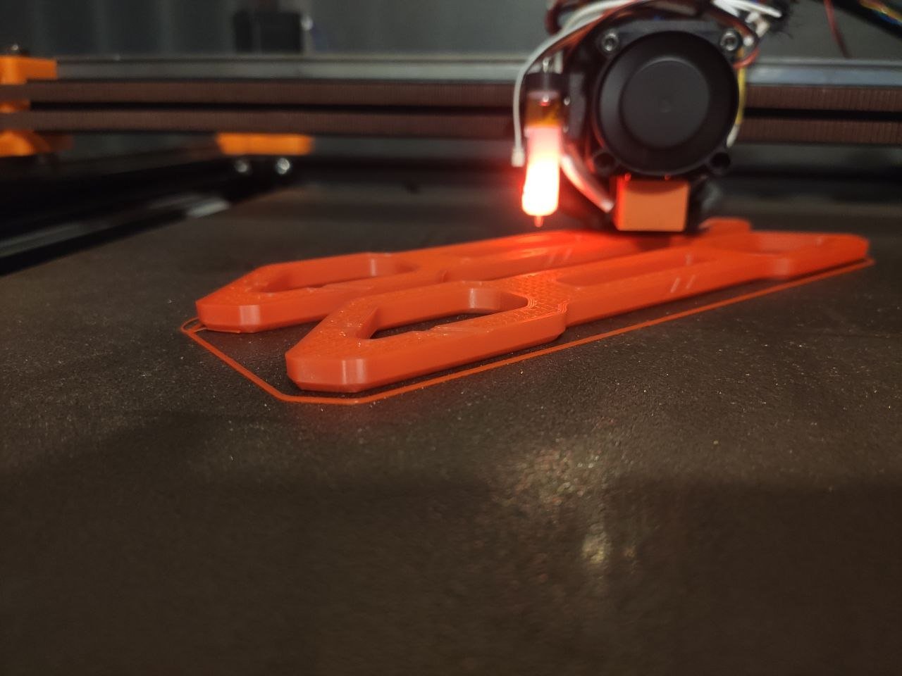
- Warping reduction – The added stiffness from carbon fibres (especially chopped) dramatically lowers shrinkage‑induced warping in high‑temperature polymers such as PEEK or PEI. DREMC tested shown reports ABS GF/ASA GF prints “10× easier” with far fewer dimensional errors and warping. - Quoted by Customer (In our experience usually much less software shrinkage compensation but more flow ratio reduction compare to based line material)
- Viscosity & nozzle clogging – Milled fibres keep melt viscosity lower and pose minimal clog‑risk, enabling higher print speeds and smoother extrusion【1】【2】. Chopped fibres raise viscosity and can cause occasional nozzle blockage, but the trade‑off is higher stiffness. So its recommended you use larger than standard 0.4mm Nozzle such as 0.5mm is good balance of details for smaller parts and minimised clogging.
- Surface finish – Because milled particles remain isotropic, they produce smoother surfaces and tighter tolerances, while chopped fibres may leave a faint fibre‑texture on the outer layers.
Choosing the Right Reinforcement
- Need maximum stiffness and strength‑to‑weight ratio? → Chopped, aerospace‑grade strands (e.g., PPS CF, PPA CF, PET CF, PBT GF, PC PBT GF).
- Prioritise dimensional accuracy, low warping, and easy printing? → Milled carbon (e.g., 15-20 % milled carbon filament).
- Design for electrical conductivity or EMI shielding? → Either type works, but higher carbon loadings (often achieved with chopped fibres) give the best conductivity.
The decisive question isn’t “how much carbon is in the filament?” but what type and geometry of carbon fibre the filament uses
Choosing the right filament for your project can be challenging. With a multitude of base materials and reinforcement types available, finding the perfect match often takes time. That’s where DREMC stands out. We go beyond being just a materials supplier; we position themselves as your technical partner as well. Need some advise or just a quick chat on our discord? Reach out.
Sources:
[1] ScienceDirect article: “Milled carbon fibres: recent advances and future prospects” (2022). https://www.sciencedirect.com/science/article/abs/pii/S1359835X22004304
[2] Wevolver. (2023). The role of reinforcement geometry in boosting 3D‑printed part performance. https://www.wevolver.com/article/the-role-of-reinforcement-geometry-in-boosting-3d-printed-part-performance
[3] VisionMiner. (2024). Carbon Fiber 3D Printing. https://visionminer.com/blogs/articles/carbon-fiber-3d-printing.
[4] I built a thing (2025). The biggest SCAM in 3D Printing? How filament stores try to trick you with carbonfiber ‘reinforced’. [online] YouTube. Available at: https://www.youtube.com/watch?v=_VbOSbOZG1Y.